Vehicular Combat

Overview
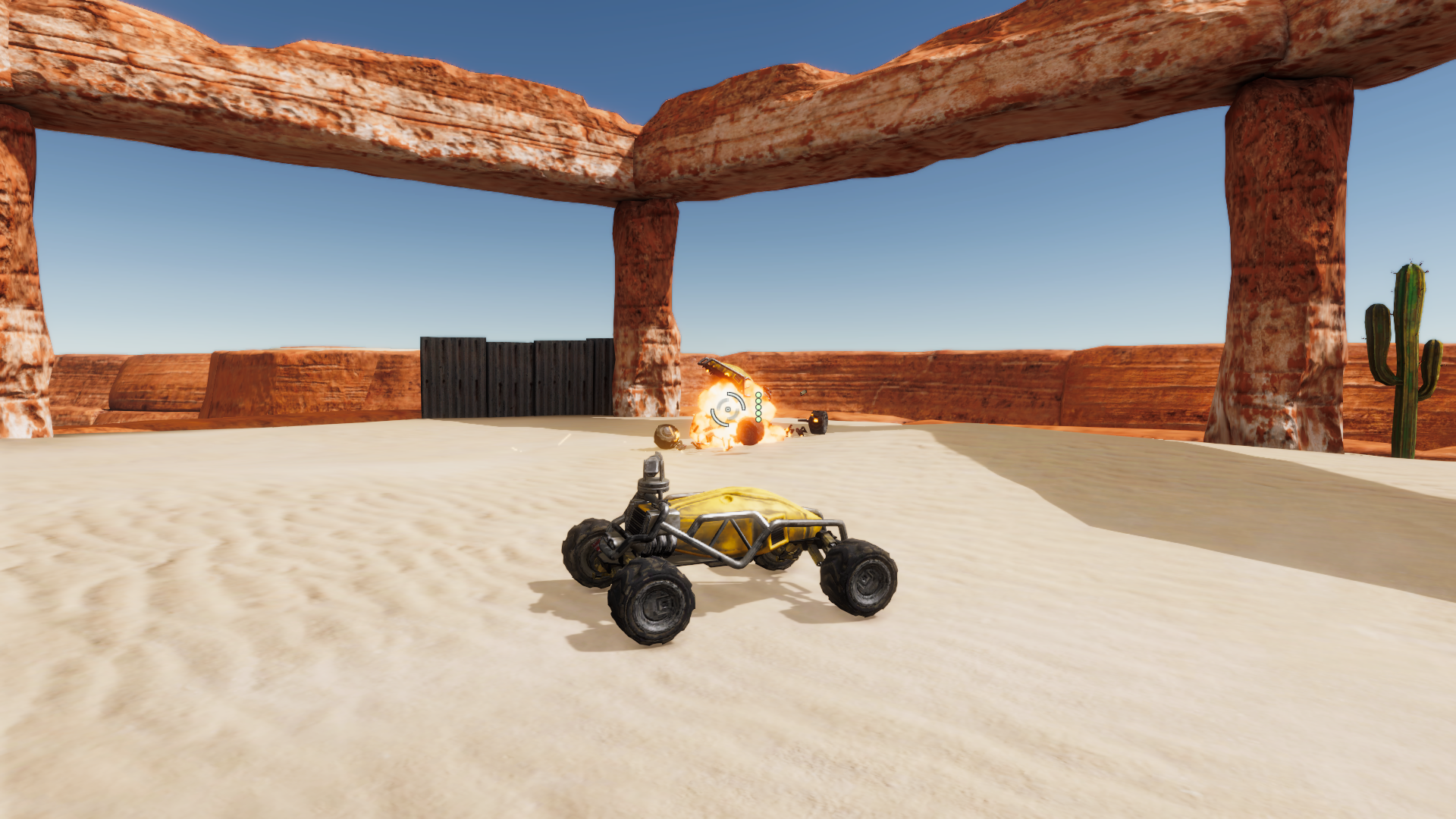
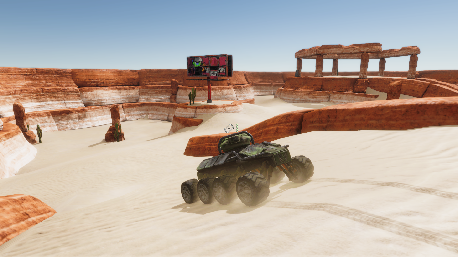
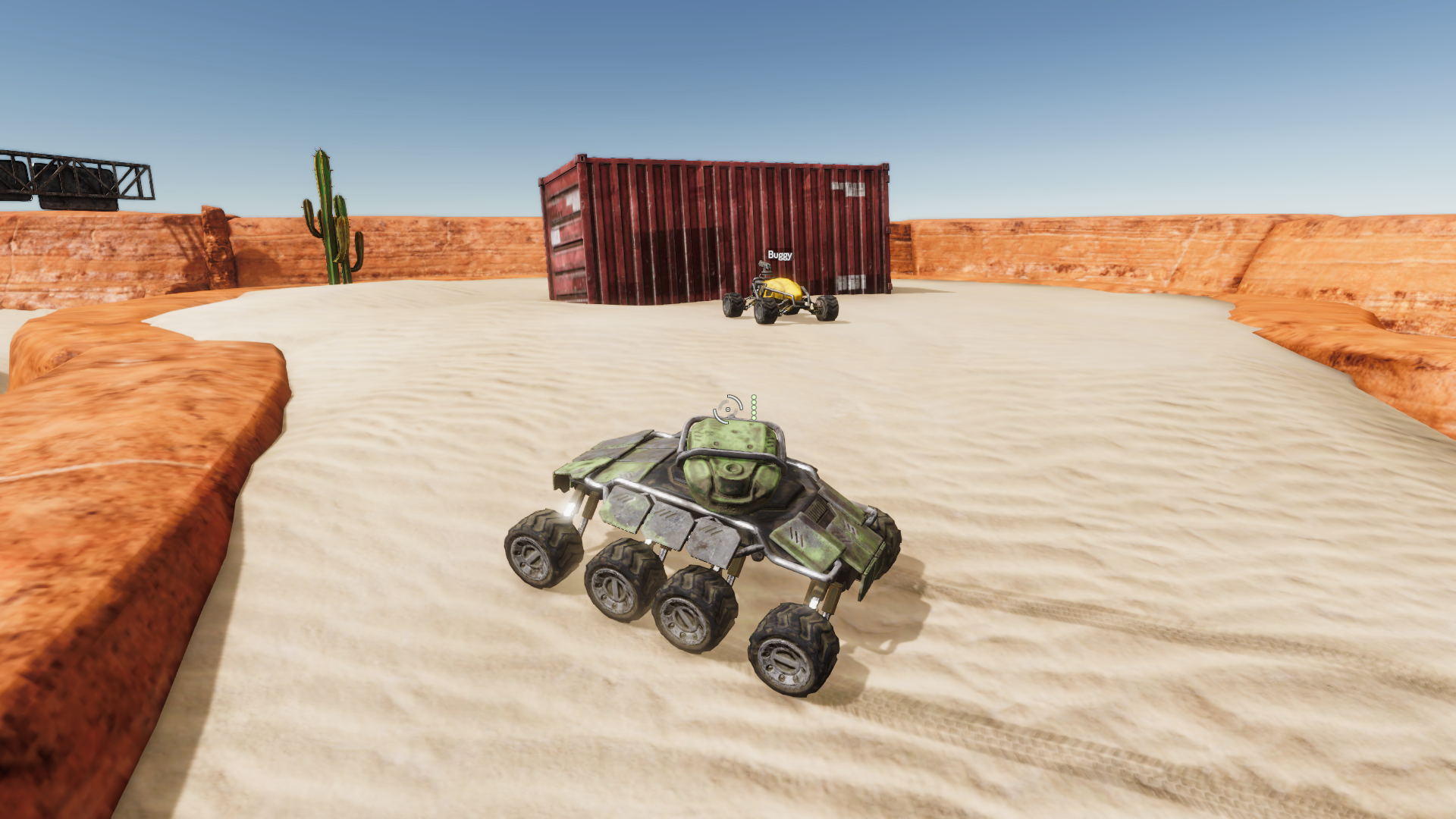
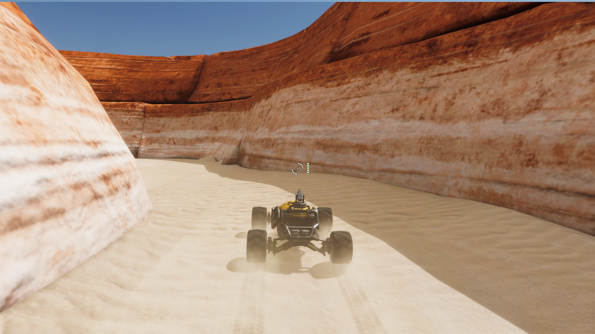
The KEO Vehicular Combat sample is a vehicular combat game built with Quantum. The samples includes two types of vehicles (a lightweight buggy and a heavy 8-wheeler tank) which are used to battle in an ongoing free for all deathmatch.
The sample was developed by Redcatpig and is based on their upcoming game KEO.
Technical Highlights
- Vehicle Controller with Driving Physics
- Multi Axis Configuration Support
- Dynamic Suspension View Formula
- Damage System
- Hitscan Weapon System
Screenshots
Download
| Version | Release Date | Download | |
|---|---|---|---|
| 2.1.8 | Mar 22, 2024 | Quantum Vehicular Combat 2.1.8 Build 343 | |
Multi Axis Configuration Support
By default the sample supports up to 4 wheel axles and 8 wheels (2 wheels per axle). It is possible to create vehicles with more axles & wheels by increasing the fixed array size in the VehicleState component; simply set it to the maximum amount axles the largest vehicle may have.
C#
component VehicleState {
    asset_ref<VehicleConfig> Config;
    DriveTrain DriveTrain;

    Byte AxleCount;
    array<AxleState>[4] Axles; // modify this value for support more axles

    [HideInInspector] FP TimeFlipped;
    [HideInInspector] FP TimeFalling;
    [HideInInspector] FP Fuel;
}
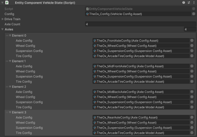
Axle Setup
For each vehicle, set the Axle Count for that particular vehicle. Each Axle requires an AxleConfig, WheelConfig, SuspensionConfig and TireConfig to be functional.
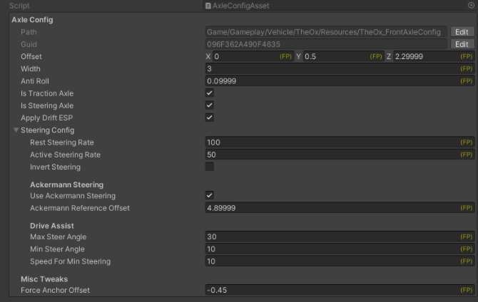
Axle Config
AxleConfig allows to set the offset of the axle which is its position relative to the vehicle's center / pivot.
Each axle may apply Traction and/or Steering. If the axle is situated towards the rear of the vehicle, and the wheels also apply steering (such as in the case of the tank vehicle), the InvertSteering option has to be checked in order for the wheels to apply the correct steering.
C#
struct AxleState {
    asset_ref<AxleConfig> AxleConfig;

    asset_ref<WheelConfig> WheelConfig;
    asset_ref<SuspensionConfig> SuspensionConfig;
    asset_ref<TireConfig> TireConfig;

    [HideInInspector] FP SteerAngle;
    [HideInInspector] WheelState WheelL;
    [HideInInspector] WheelState WheelR;
}
Drive Assist
In the Drive Assist section, the max and min steering angles for each steering axles. This helps players not oversteering or losing control at higher speeds.
Suspension
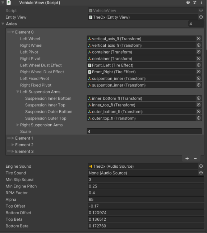
The suspension is visualized on the Unity-side by reading the values of the car physics in the Quantum simulation. The class responsible for this is called AxleView.cs.
As this is pure visual representation, the suspension visual reacts to the simulation but the suspension itself is not part of the simulation. Thus the following section are entirely about Unity-side representation and code.
Dynamic Suspension View
The formula included in the sample for the custom suspension view is specific to the type of suspension created in KEO's vehicles, but the logic can be adapted for other suspension types.
The suspension is composed of:
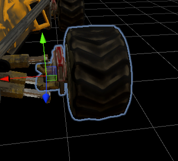
- Left/Right Wheel: The visual wheel which will rotate on its X axis according to the vehicles movement.
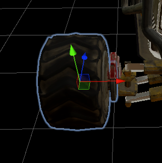
- Left/Right Pivot: The object of which will get its Y position set according to the suspension compression (taken from the Quantum Simulation), and will rotate on its Y axis to simulate steering (wheel objects must be children of the pivots).
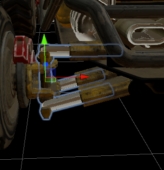
- Left/Right Fixed Pivot: The object which will be synchronised with the wheels Y position and contains all "inner" parts of the a suspension bar (explained below).
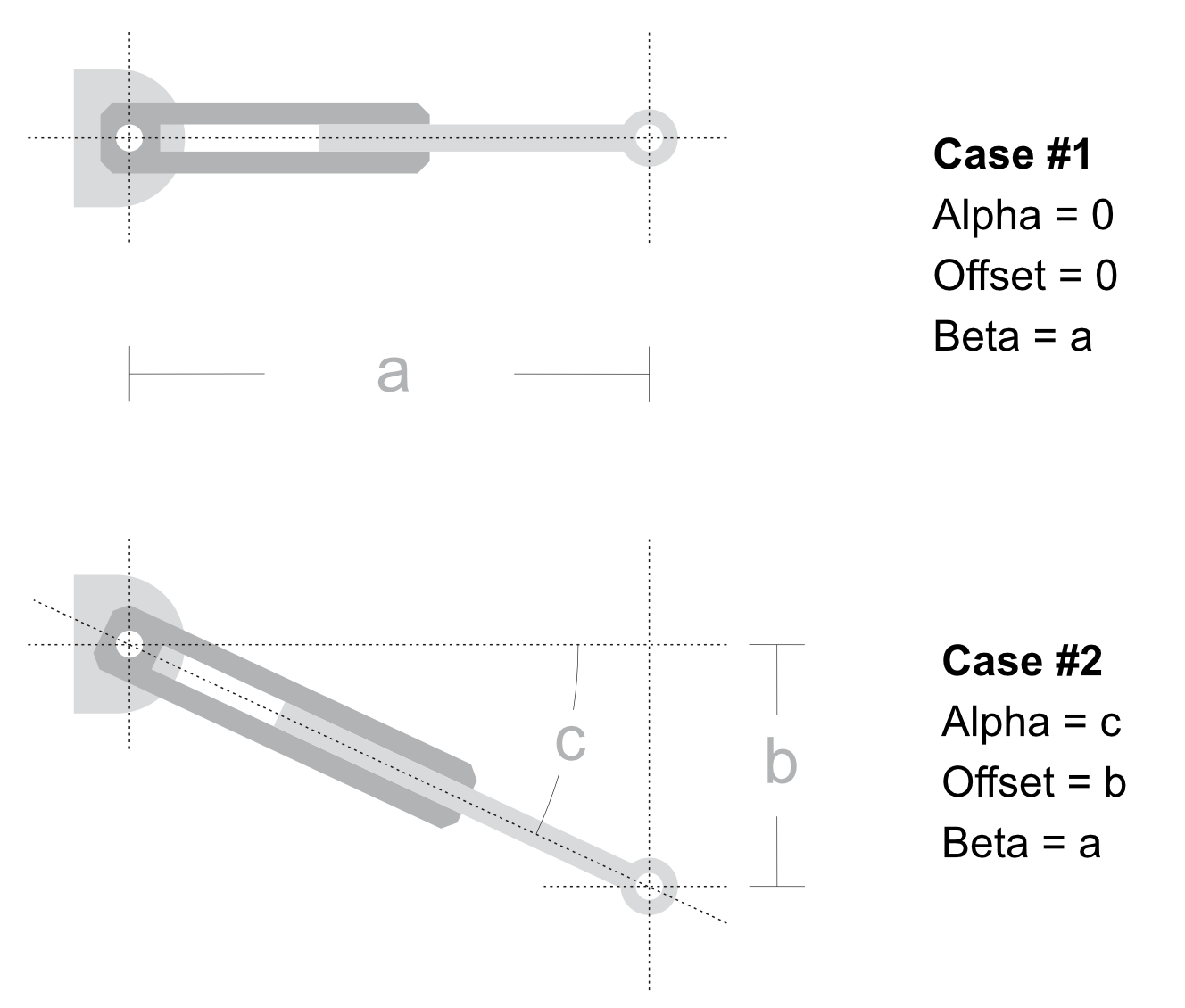
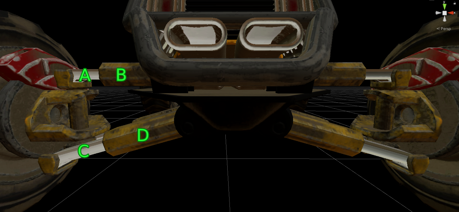
Suspension Formula
The suspension bars are composed of an inner top bar ( A ), outer top bar ( B ), inner bottom ( C ) and outer bottom ( D ).
The formula driving the visuals is the following:
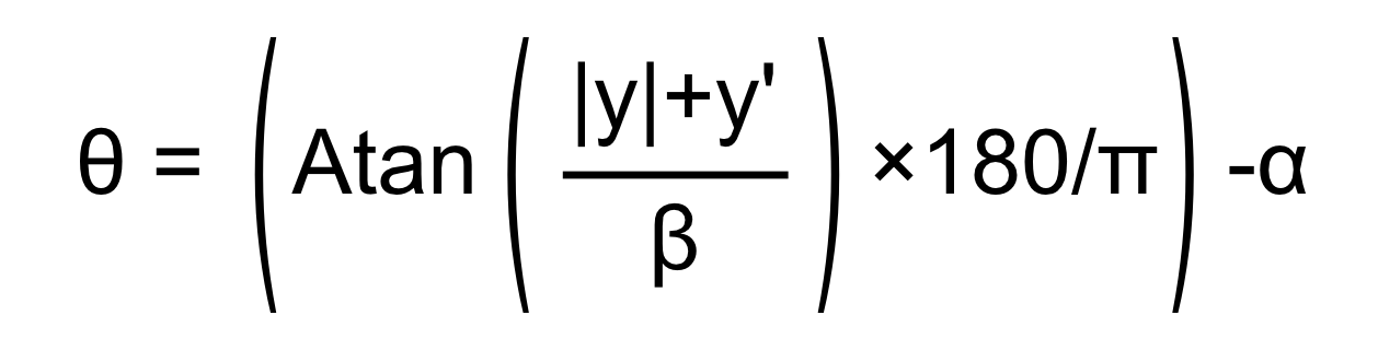
The idea behind the formula is to simulate a hydraulic bar opening and closing by taking the wheels Y position, and rotating the inner and outer suspension pieces accordingly.
For this the starting angle (Alpha) of the given suspension arm is required. The starting angle is always 0 for the top bar (Case #1), and must be measured for the bottom bar (See Alpha in Case #2 in the diagram below). The Offset, i.e. its initial Y distance from the position where the bar rotates, is also needed (See Offset in Case #2 in the diagram below). Lastly, the length of the suspension arm (Beta) when completely parallel to the worlds X axis (See Beta in Case #1) has to be accounted for. The best way to measure these values is using whichever 3D Software was used to create the vehicles.
C#
LeftPivot.localRotation = Quaternion.Euler(0, axleState.WheelL.SteerAngle.AsFloat, 0);
RightPivot.localRotation = Quaternion.Euler(0, axleState.WheelR.SteerAngle.AsFloat, 0);

if (vehicleViewUpdateData.VehiclePhysicsBody->IsSleeping)
{
    return;
}

// update wheels suspension travel
var suspensionMaxTravel = _suspensionConfig.MaxTravel.AsFloat;

var leftSuspensionCompression = axleState.WheelL.Suspension.CompressionPrevious.AsFloat - suspensionMaxTravel;
var rightSuspensionCompression = axleState.WheelR.Suspension.CompressionPrevious.AsFloat - suspensionMaxTravel;

LeftPivot.localPosition = _leftPivotPosition + new Vector3(0, leftSuspensionCompression + _anchorOffset, 0) / Scale;
RightPivot.localPosition = _rightPivotPosition + new Vector3(0, rightSuspensionCompression + _anchorOffset, 0) / Scale;

LeftFixedPivot.localPosition = _leftFixedPivotPosition + new Vector3(0, leftSuspensionCompression + _anchorOffset, 0) / Scale;
RightFixedPivot.localPosition = _rightFixedPivotPosition + new Vector3(0, rightSuspensionCompression + _anchorOffset, 0) / Scale;
C#
float angleTop;
float angleBottom;

if (wheelLocalPos.y < 0)
{
    angleBottom = (Mathf.Atan((Mathf.Abs(wheelLocalPos.y) + _vehicleView.BottomOffset) / _vehicleView.BottomBeta) * 180 / Mathf.PI - _vehicleView.Alpha) * -1;
    angleTop = (Mathf.Atan((Mathf.Abs(wheelLocalPos.y) + _vehicleView.TopOffset) / _vehicleView.TopBeta) * 180 / Mathf.PI) * -1;
}
else
{
    angleBottom = Mathf.Atan((Mathf.Abs(wheelLocalPos.y) + _vehicleView.BottomOffset) / _vehicleView.BottomBeta) * 180 / Mathf.PI - _vehicleView.Alpha;
    angleTop = Mathf.Atan((Mathf.Abs(wheelLocalPos.y) + _vehicleView.TopOffset) / _vehicleView.TopBeta) * 180 / Mathf.PI;
}

if (leftSide)
{
    angleTop = angleTop < 0 ? Mathf.Abs(angleTop) : angleTop * -1;
    angleBottom = angleBottom < 0 ? Mathf.Abs(angleBottom) : angleBottom * -1;
}

suspensionInnerBottom.localRotation = Quaternion.Euler(new Vector3(0, 0, angleBottom));
suspensionInnerTop.localRotation = Quaternion.Euler(new Vector3(0, 0, angleTop));
suspensionOuterBottom.localRotation = Quaternion.Euler(new Vector3(0, 0, angleBottom));
suspensionOuterTop.localRotation = Quaternion.Euler(new Vector3(0, 0, angleTop));